
Specializing In Having Fun!
Building The Sleigh
From This

To This

From concept to reality, this was a monumental project with many hundreds of hours of time and labor invested. A good amount of trial and error was involved, and at times, design compromises needed to be made. Even after 2 years, more surprises and improvements to its current design are expected to be added. Ready for action, yet more to come!
Read on to see how this unusual idea became reality!
Brainstorming
The idea of a multi-faceted, year-round sleigh was ambitious. And an engineering challenge. Did anyone else have something like this? It was soon determined that the "competition" was limited pretty much to one time of the year. What could be done to make this one unique and stand out? It was decided to add unusual features to give the sleigh versatility and entertainment capabilities. With so many elements, how would all the components fit together? How much would this cost? And, perhaps, most critically, how do you make people understand that this was not just some glorified lawn ornament? After all, the proposed ideas were way over the top. And so, it began.


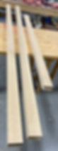
Choosing The Wood
With its beautiful grain and a propensity not to rot, red cedar was chosen to become the outer walls. Several trees were cut down and sliced into boards that could be milled later.


Wood Cutting Videos


The Frame


To handle future weight that was estimated to approach 2500lbs without passengers, the frame would need to be very strong. A combination of thick gauge steel tubing and channels were cut to specifications and welded together. The frame was estimated to weigh 400 lbs. To inhibit rust, it was coated with rustproofing paint. More welding modifications would need to be done in the future.

The Frame: Delivery Video

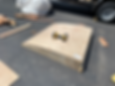
Wood Preparation
This likely was the most arduous part of the project with many hours spent at the woodshop. All of the rough planks needed to be crafted into precise and stackable wall pieces. Pieces were hand selected, cut, jointed and planed before being glued together into blocks. To ensure there would be enough red cedar for the exterior walls, 1x3 pine boards were glued to the back of the red cedar pieces. The blocks were then sanded and planed again to exact matching heights and thicknesses before being cut into various lengths. The pieces were organized and grouped together according to their final lengths. In the end, around 400 linear feet of blocks for the walls were produced. Additional time was spent milling many of the oak portions of the sleigh as well.


Wood Shop Videos


Adding The Subfloor
As the build commenced, the initial focus was on the sleigh base. Pressure treated 2x4s and waterproofed 1" marine plywood were bolted to the frame. The actual sleigh floor would come later.


The Sleigh "Dolly"
While this was to be heavily modified later, the first rendition of the sleigh dolly needed to be built to make the structure more transportable. This was done by bolting channel struts and industrial 10" solid pneumatic caster wheels into a frame with 1/2" bolts. Each wheel is rated for 1000lbs. Swivel wheels were purposefully selected for the front to enable right and left turns. The 4x6's not only added strength and stability but also were the perfect height to raise the runners off the ground by 4".


The Sleigh "Dolly"Video

Adding The Base Elements
For the curved accent trim, two 13 foot long, 1" schedule 40 pipes were ground to bare metal, bent, and painted silver. To bolt them to the sleigh, corresponding holes were drilled through the pipes and into the step thresholds. Later on, these modified pipes will have wires strung through them and be outfitted with traffic lights. Oak planks were glued together with 2x4s and added to the perimeter of the frame. These will end up forming the base of the sleigh walls and are stabilized by 2-inch welded steel tabs that protrude from the frame. Further stability is provided by bolting the wood to the outside of the frame. After the metal frame is sanded, primed and painted, two steel struts were bolted onto the rear to support a needed sleigh body extension. This extension was added to create space to accommodate a future hidden compartment. The initial steps and stair treads were added and a pre-built center console was mounted. To ensure that the snow machine would fit inside, a section of plywood inside the center console was cut out to lower the floor.


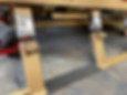
Selecting The Wall Pieces
Both sides of the sleigh walls had to mirror each other for the chassis to rise evenly. Blocks were hand selected based on wood grain patterns to make both sides look similar. To accomplish the desired build, the blocks for each side were hand stacked facing each other on two different tables. Then, each block was numbered piece by piece and row by row for its future placement.


Building The Walls
To prevent splitting, each and every block had to be predrilled wherever a screw was going to be. Two different drill sizes had to be used for each hole. The wider hole was for countersinking the screw head halfway into the block, while the smaller hole was for the screw itself. The goal was for each screw to be halfway into both the upper and lower block. The build was a very tedious process. One block at a time, marks were made, and the wide holes would be drilled first. The block would then be held in place by hand to drill the smaller holes through into the block below. Extra strength wood glue would then be applied to both the upper and lower blocks before screwing the block into place. This unconventional method would result in an incredibly strong wooden "shell".


Corners And Angles
The two rear corners had to be aligned perfectly in the same plane and tilted 8 degrees backwards while at the same time on the bottom, tilt 4 degrees sideways. To accomplish this, extra-long blocks were placed vertically in the corners. These were held in place by airborne planks placed on ladders. The blocks forming the first two rows on each side were cut lengthwise at 4-degree angles to flare out the bottom. Cutting the next two rows at 2 degrees created a slight bend and brought the walls to level and plumb by the 4th row. To get the horizontal row of blocks flush with the tilted vertical ones at each corner, 8 degree and 4-degree cuts were made to the abutting horizontal blocks.


Profile, Cutouts And Tail
Aluminum ramps provided the template for much of the sleigh profile. Cutouts for the future speakers and lantern shelves were made. A rectangular opening on the bottom in the back of the sleigh would be for the battery charging port and a decorative "license plate". A removable "tail" was added. Afterwards, the entire "shell" was rough, and finish sanded.


Pre-Stain "Shell" Video

More Welding
The front of the sleigh frame was extended to provide support and additional flooring for the soon to be built front portion of the sleigh. To do this, the front portion of the plywood subfloor was cut off to be reused as the lowered floor. At the same time, the beginning of the hitch apparatus was constructed by drilling holes in the angle iron for a three-foot-long steel pipe.


More Welding: Videos


Constructing The Front Hood
To build a sloping hood, curved forms were made, and two pieces of 1/4 inch plywood were glued and screwed together on the curve. After the glue dried, the forms were removed. Then red cedar "strips" were glued and screwed to the plywood shell and sanded.


Building The Front End
Curved oak and pine "fenders" were made by gluing and screwing angled blocks. The compartment was framed out, reinforced with metal plates and brackets, and the floor installed. The hood was then cut to fit between the "fenders" and attached with heavy duty hinges. Cement board was cut, attached to the sides and tiled with a brick veneer. Later on, removable red cedar panels would be built for these areas to allow for wood or brick side options.


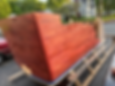
Staining The Wood
Staining the wood was a three-step process. First, wood conditioner was applied to ensure even penetration of the stain and highlight the grain. Red crimson oil-based stain was thinned out at a 5-1 ratio and copper flecks were mixed in. This was then applied to the red cedar wood surface with absorbent pads. After drying for a day, two coats of marine grade spar urethane were applied. The end result was wood that looked almost translucent with a bit of a sparkle.


Adding The White Trim
Originally, white weather stripping was used on top of the walls. While at first it looked nice, it was found that this material was not durable enough, becoming dirty and torn over time and was eventually replaced. For a finished look that was durable and weather resistant, using strips of PVC molding fastened with finish nails was a much better option.


Building The Snow Machine Floor
Two L beams were welded to the frame to hold a lower floor section that would support the snow machine box. This was the only way to get the snow machine box low enough to fit under the center seat. These beams were strategically placed to hold the dolly in place as well.


Adding The Shelves And Lanterns
Custom shelves cut out of oak planks were built for attaching the lanterns. Originally solar, the lanterns would be converted to electric later.


Rear Compartments and Seat
The entire rear area was designed to be accessible with sliding or removable panels. The space under the rear seat would house the ground fog machine. The far rear compartment would eventually hold the snow machine hose and the air lift compressor.


Adding The Wiring Channels and Finish Floor
A critical design element for hiding and protecting much of the sleigh wiring was the creation of space between the subfloor and finish floor. This was done in the front and the back of the sleigh. The use of pressure treated 1"x1" balusters screwed to the subfloor worked quite well for this. While these supported the finish floor, they also created "channels" for any wires. Openings at the bottom of the center console were be cut to allow wires to run from under the hood all the way to the back of the sleigh. For access to the wires, the floor panels are designed to be removable. Also at this time, a partition was added to enclose the hood area. The temporary top rail would be replaced later.


Adding Sleeves
These would be important for giving the sleigh immeasurably more customization and functionality. 1 1/4" galvanized pipes were cut and built into the rear compartment and center console area. Eventually a total of 8 of these were installed.


Beginning The Upholstery
For the rear seat, two separate padded sections were built using plywood, foam, and outdoor fabric. These were designed to be easily removable for access to the rear compartments.


Upholstery Prep
The interior walls were sanded smooth to ensure good contact of the fabric to the wood. A spray adhesive was used to glue the fabric to the wood. The center console was temporarily removed to make this work easier and for the console itself to also be upholstered.


Finishing The Upholstery
All exposed interior wood was covered in fabric. The center console was prepped and sanded before covering. The front panel was temporarily removed to be upholstered and the top of the back compartment was done as well.


Adding Accents
As the upholstery was being worked on and completed, an oak beam was added on top of the hood along with a new reinforced rail. Finish molding was added on the edges of the this beam. 1/4" oak panels were added to cover any exposed 2x4s and give a finished look. Decorative wood molding was stained and added. Wood molding was added to the perimeter of the console cover for a decorative look. A wrought iron sleigh ornament was added to the tail. This is also when the white weather stripping on top of the walls was removed and replaced by PVC.


Adding The Dashboard
The box for what was eventually to become a fully functional dashboard was built. The front panel was cut out and the dashboard box was attached. The back of the box was left open for wiring. The gap between the dashboard and the top beam would eventually be bridged by an oak panel.


New Steps, Treads, Rear Box
It was discovered that the original steps, which were made of a composite material known as Trex would become soft in the heat and direct sun. As a result, when stepped on, the steps would sag considerably. They were removed and replaced with new steps built out of oak which matched up well with the oak base. To prevent potential slips, stair treads were attached. Aluminum treads were added at the edges of the rear sleigh floor for a finished look. The gaps between the floor and the walls were intentional for placement of LED light strips later for interior accent lighting. A box was constructed and inserted into the rear cutout. An RV plug for battery charging would end up here.


Center Seat Construction
The building of the center seat ended up being a major project all on its own. 2x8 boards were cut into staggered lengths. 2x4s were used for both seat corners. Difficult cuts were needed to be made to make them all fit together in such a way that the seat would curve and lean backwards at the same time. This was accomplished by a series of 8 degree and 4-degree bevel cuts on the bottom and sides of each piece. They all were screwed and glued together and attached on 3/4" plywood.


Center Seat Upholstering
A combination of foam, gray marine vinyl and upholstery nails comprised the front while red outdoor fabric was glued to the back. PVC strips and black spray paint finished it off.


Attaching The Seat To The Center Console
Because the sleigh had no rear doors to the back seat, the center seat was designed to swivel left and right to allow passage from the front to the back. To do this, a heavy-duty Lazy Susan that can support up to 1000 pounds was screwed to the top of the center console and to the bottom of the plywood supporting the seat. Over time, trim would be added, and the bottom of the seat would be redone from gray to red. To hold the seat in place, holes were drilled and two pins inserted. These pins were easily removable to allow it to swivel.


Swivel Seat Demontration Video

Making The Runner Extensions
This required a bit of outside the box thinking. Blocks of wood were cut at varying degrees of angles to create curves. These were then glued and screwed together before being sanded smooth. Decorative milled wood from Home Depot were customized by sanding the square moldings round and then gluing them back-to-back. These "swirls" were then glued to the end of the curved wood and painted. To attach the wood to the metal runners, holes were drilled through the runners. Brackets were customized to be screwed to the bottom of the wood attachments and then bolted to the runners.


Speaker And Outlet Cutouts
Six cutouts were made for the speakers (two additional speakers would be tower speakers) Other cutouts were made for two GFCI outlets in back. A third GFCI would be added in the front later.


Converting The Lanterns
To have control over the lantern lights from the dashboard and to give them more impact, they were converted from solar to electric. After being taken apart, the interior solar components were removed. Instead of hooks for hanging, rods from a pendant kit were cut and, after cutting off the lantern tops, the threaded end of the rods were fastened to the lanterns with hex nuts and washers. For the incoming power wires, holes were drilled through the "roof" of the lanterns and grommets inserted into the holes to protect the wires. Candelabra sockets were cut off of cord sets and wired to the power wires. Dimmable incandescent bulbs were screwed into the sockets and the pieces put back together. Attaching to the shelves was accomplished by inserting wooden dowels inside the top of the hollow rods and screwing downwards into the dowels through the oak shelf.


Building The Two Fog Distribution Systems
This proved to be one of the most challenging aspects of the sleigh construction and required a lot of thought, fabrication and testing to pull off. Careful consideration and foresight were needed. How were things going to be laid out cohesively in the underbelly of the sleigh? Everything was going to have to fit somehow - the ductwork, pipes, inline fans, dolly, air bags, air lines, underlighting, front hitch, and snow machine hose. Both fog systems would require the installation and wiring of in line fans to get them to work properly.
The first system to be worked on was the one involving one of the most powerful commercial foggers on the market, the M-11 dual fog machine. This machine was to be hidden under the front hood on the floor. Because of its tremendous heat output, custom made car exhaust pipes had to be used at the fog entry point. With the M-11 being a dual fogger, two separate fog runs could be created. One run was built into the center console and the other ran out to two tailpipes in the rear. The inline fans ensured that no fog would back up into the hood compartment.
First System: The Smoker


Smoke Test Video

The Second System: Ground Fog
The second fog system was no less of a challenge. Because it was a ground fogger there were no concerns about heat. To have distribution channels that would fit under the sleigh and not interfere with other sleigh components, galvanized metal framing studs were taped together and run inside the frame. Holes were drilled every two inches into the studs to allow the fog to disperse evenly underneath the sleigh.


To get this to work, a hole needed to be cut through the rear subfloor. A home roof vent was customized to "catch" the fog above this hole - directing it into a custom built "pan" below the floor. From here, two inline fans were needed to draw the fog from the fog machine into the pan and push the fog through the distribution system.


Ground Fog Test Video
Adding The Machine and Fan Controllers
There were 3 machine controllers and 4 variable flow inline fans. The controllers for the snow machine and the ground fogger were mounted on either side of the dashboard. The two fan controls for the M-11fogger were mounted below them. A switch on the dashboard would control the remaining 2 inline fans for the ground fogger. The machine controllers have magnetic backs which allowed for them to be placed on metal brackets. The controller cables were more than 20 feet long and threaded through the wall. This combination of magnets and wires allowed the controllers to be lifted off the brackets and, if needed, operated at a distance. The cables had to be run throughout the sleigh to each machine and fan. The controller for the dual fogger was a remote and not mounted.


Running The Wires and Connecting the Electrical Components
All kinds of wires needed to be run throughout the sleigh and labeled for future connections. Speaker wires, 120v wires, 12v wires, cables...etc. Just about every wire was run through under the floor. Five interior electrical boxes were mounted and wired. Three were for the machines to be plugged into, one was for providing power to the ground fog inline fans, and another was wired onto the back wall of the far rear compartment for future options.


Building the "Stage"
The idea to add a platform was conceived from the very beginning. The center console and rear seat of the sleigh were purposefully designed to be removable and to be at the exact same height. Removing the front and back seats allowed for inserting a portable bifold floor for even more sleigh conversion possibilities. A one-inch thick 4x8 sheet of plywood was cut to 4x6 before being cut lengthwise down its center. Sturdy hinges were attached to enable folding. A hole was cut in the center to allow for any use of the center sleeve. While any rug would work, a roll of artificial grass was cut for a surface.


The Construction of The Dolly and Air Bag System
This probably required the most impressive engineering of the entire sleigh project. The idea of a removable dolly with attachable air bags was conceived at the very beginning of the sleigh project. While the first rendition of the dolly had served its purpose well, it could not be trusted in real world situations. The concepts of strength, safety, functionality and convenience were revisited, and the final design was updated. It was determined that the only way for this idea to work was to raise the sleigh leg height by four inches. This was needed to fit the airbags between the dolly and the frame. As a result, the first step would be to cut off the legs and runners and weld on extensions. After reattaching the legs, rebar was welded to the bottom of each runner to ensure better traction and performance in snow. The legs were then repainted.


The Airbags
Next, the airbags were assembled and welded to the four furthest corners of the frame. These were incredibly strong. Each bag was rated to hold 6,000 pounds.


Airbag Demonstration Video

The Compressor
To make the bags work required the creative modification of an old air tank. For space considerations, the tank, compressor and air valves had to all be made into one mechanical unit. Three holes were made in the tank and three "stems" were welded onto the holes. These "stems" held wired valves that enabled control of the intake and the release of compressed air. A metal plate was also welded on for mounting the compressor. Part of the sleigh back wall had to be shaved to get the unit to fit correctly. The air lines, protected inside flexible conduit, were run to each air bag unit. A customized control pad was built with buttons/switches and an air pressure gauge and fastened to the dashboard


Modifying The Dolly
The sleigh dolly was a critical, and very unique design element of the sleigh. It would have to be incredibly strong for the forces it would have to endure and have the capability of flexing slightly for road conditions. The air bags had to be safely secured to the dolly. Steel plating, a brace, and rebar were welded onto the channel struts to give it more strength. Metal "eyehooks" to fit in the center of the struts were welded on to the bottom of the air bag plates. These hooks allowed 5/8" pins to be slid into holes drilled through the reinforced channel struts to hold the dolly to the sleigh. To make sure the sleigh would drop straight down in a vertical plane when the air was let out, steel rods were attached to the dolly which would levitate when the air bags were inflated. These "stabilizer" rods were attached by pins to the sleigh frame. In total, 8 pins connect the dolly to the sleigh. To remove the dolly, the sleigh is lowered to the ground and the pins pulled. The dolly and wheels were painted flat black to hide it from view.


Dolly Lift System Demonstration Video

Front Hitch Completion
A "tongue" was fabricated and welded to the front hitch pipe. The pipe and pin design allowed for it to swing upwards for use and to be removed if necessary. A bit more strengthening was done to the hitch frame as well.

Wood Panel Improvements
The original wood paneling had been attached to stiff PVC backing. These panels were held in place by screws and galvanized wire threaded through holes in the brick grout seams. This did not work well with the heat from the sun causing the panels to warp. The solution to this problem was to use 1/8" thick galvanized metal sheets and make new panels. Three 1/8" thick threaded bolts were welded on the back of each panel that lined up with holes drilled through the grout and wood framing. All new red cedar strips were created to 1/4" thickness, glued on, stained and polyurethaned. The panels were held on by wingnuts inside the sleigh hood. The result was a vast improvement in every way.


Adding The Tower And Side Speakers
Poles that came from a canopy frame were found to fit perfectly inside the pipe sleeves with no wiggling. As a result, it was decided to make them the marine tower speaker mounts. They were cut to a desired length and 1" L brackets were welded at one end of each of the canopy tubes. The speakers were attached by bolting their mounting brackets onto the L brackets and screwing them together. The poles were painted black. The converted tubing worked quite well for allowing the tower speakers to be moved to either the front or back of the sleigh and swiveled in any direction.


Two Listening Zones
In all, a total of 8 speakers were installed comprising of two listening zones. One zone inside the sleigh and one zone outside. Both zones can be played simultaneously if so desired. An additional receiver was installed to enable a microphone capability for actors or PA purposes.


Finishing The Dashboard
This was a continual work in progress as components were added. There was no original design, and things were thought out as best as possible in advance. As a result, the cutouts were done in stages while anticipating the future. With the addition of the receiver, all of the dashboard components were finally in place. In addition to the receiver, there was a voltmeter, clock, air pressure gauge, compressor switch, 4 air bag buttons, air release button, lantern dimmer switch, 3 machine switches (2 foggers and snow machine), 2 interior light switches, 1 switch to the hidden rear compartment electric box and 6 LED light switches. Another "dummy" switch was in anticipation of building a telescoping actuator in the rear compartment. With the exception of the black switches, everything had backlighting. Additional lighting for the dashboard would be mounted in the overhang above.


Accessories
A 14' towing bar was made out of 2x3" steel tubing. A coupling was welded on one end. The end that connected to the sleigh was strengthened and widened to allow the hitch tongue to insert inside the tubing. Doing so kept the bar in a fixed straight position so it would not slam into the runners on turns. A hole was drilled through the tubing for a 5/8" pin to attach the tow bar. This tow bar, while initially is for parades, is also expected to be adapted for animal towing later. A separate T-bar was created for the purpose of pulling the sleigh out of the trailer and to move it around.


Tow Bar Video

Final Stage: Adding The Batteries, Lights And Connecting Everything
Finally, the time came to add the rest of the final components of the power, audio and light systems and connect everything. A 5000-watt inverter, 4 rechargeable batteries, LED underlighting, front and rear "taillights", a microphone receiver, and RV plug were added. Labels were added to the dashboard. Everything worked. An incredible project was ready for action. The sleigh was now alive!


Green Light And Sound Video
